Tutorial 1: A Quick Walk-Through
This tutorial provides a quick overview of the core functionality of CVM without going into
great detail. It also shows how the different parts of CVM - the model editor, diagram
editor and the VSL editor - fit together.
Prerequisites
For this tutorial, you need an installation of Eclipse with CVM, either as a stand-alone
RCP version or as an Eclipse plugin. For more information on installation please refer
to the CVM manual, section "Installation".
Creating a New File
We start by creating a new model file. Such model files have the extension ".cvm".
| Plugin Version | | RCP Version |
- In Eclipse, select from the main menu "File / New / Other ...".
- In the dialog that opens up, select file type "CVM Variability Model" from category "CVM"; then click "Next".
- Choose a container (i.e. an Eclipse project to contain our new file).
- Change the file name to "tutorial1".
- Select to create an empty file.
- Click "Finish".
| |
- In the RCP version, select from the main menu "File / New CVM File ...".
- Choose a folder and file name in the dialog and click "Save".
- Select to create an empty file.
|
This opens up the CVM model editor showing our newly created file. As you can see, the file
has already been populated with a single root element of type VariabilityModel. Such a
variability model is the root container for all information managed by CVM.
The default name for this is "New Variability Model". To change this name, double-click on the
name of the element in the model editor and type "VM" and press Enter.
Creating a Simple Feature Model
To add content to our variability model we will now create some Features. Features cannot
be contained directly in a variability model; instead we first have to create a FeatureModel.
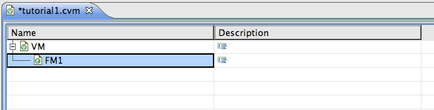
- Right-click the variability model element, now called "VM", and select "New Child / Feature Model"
from the context menu.
- Expand the variability model element (by clicking on the "+" symbol).
- As above, rename the newly created feature model by double-clicking on its name. Call it "FM1".
Now, your editor window should look similar to this:
In this feature model, we now define the variability of a wiper in a fictitious car product line:
Example 1:
The wiper comes in two core variants: a simple and an advanced form. In the second case,
more sophisticated interval modes are provided. In addition, the wiper may provide an automatic
mode in which wiping is controlled depending on the current rain intensity. All our cars have
such a wiper.
To create the features for this example, you have several options:
- Right-click the parent feature (or feature model) and select "New Child / Feature" from the context menu.
- Select a feature (or feature model) and press ALT+C to create a child feature or press ALT+S to create
a new sibling feature.
- Select a feature (or feature model) and click the button
 on the CVM tool bar.
Obviously the simple and advanced forms of our wiper are alternative, so we need a feature group of
cardinality [1]. To create such a feature group you again have several options:
- As for features above you can use the "New Child" context menu action, use a keyboard short-cut
(ALT+G for create ggroup, in this case), or the tool bar.
- Alternatively, you can select two or more sibling features which are not grouped yet and
select "Group Features" from the context menu. This will create a new feature group and add the selected
featues in a single step.
Finally, to set cardinalities use the context menu and to edit the feature's names and descriptions
double-click on them in the model editor.
The complete feature model for the above example then looks like this:
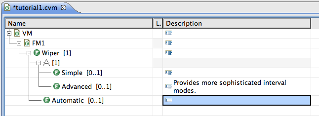
Note that we have set feature "Wiper" and the feature group to cardinality [1].
Feature Modeling in the Diagram Editor
To illustrate configuration links later in this tutorial, we want to add a second feature model. We could do
this as before for "FM1", but let's use the diagram editor for this.
This is what we want to model:
Example 2:
In contrast to the rather end-customer oriented variability specification in feature model "FM1"
above, we now want to specify our wiper's variability on a more technical level. It may have
different forms of wiping modes and may have a rain sensor. A continuous wiping mode is always
present. In addition, an arbitrary number of interval modes can be chosen during configuration.
Finally there is the option of a flexible interval mode, where the driver can adapt the duration
of the wiping interval by rotating a special button.
First, we need to create a variability diagram. So:
- Right-click the root variability model and select "New Child / Variability Diagram" from the context menu.
- Rename the new diagram to "VD".
- To now open the diagram editor, please right-click our diagram "VD" and select "Open Diagram" from the context menu.
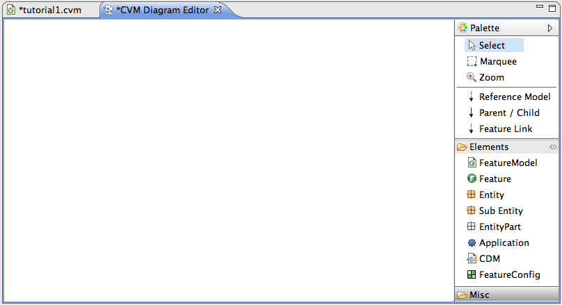
This opens a new editor window showing an empty diagram.
- Make sure to expand the tool palette on the right side of this window; you might have to click on the little
arrow on the right side.
If everything went smooth you will see something like this:
Creating a feature model here in this diagram is pretty straightforward:
- In the palette, click on the tool for creating feature model (called "Feature Model", located in the "Elements" tool box).
- Now click somewhere in the diagram. A new feature model will appear.
- The name is already selected for direct editing. Type "FM2" and press Enter here.
- Enlarge the feature model's visual to make room for contained features, by clicking and dragging the lower-right corner of it.
(NOTE: In the future, you can create and resize an element in one go by clicking and dragging in step 2 above.)
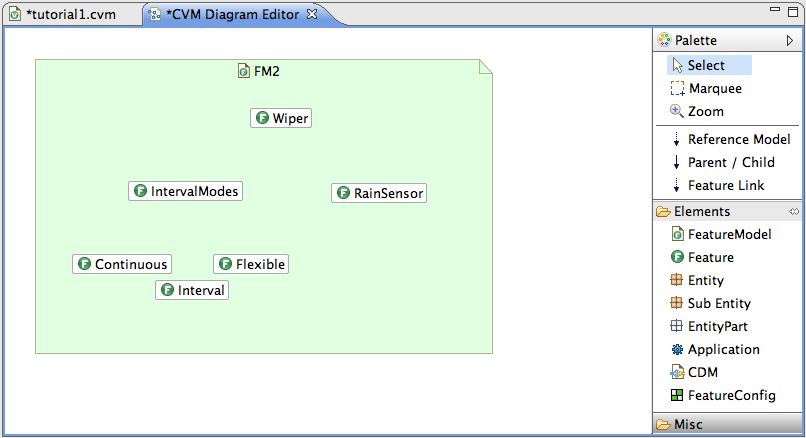
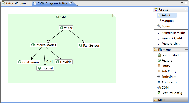
In the same way create 6 features and rename and arrange them as shown in the following screenshot (don't resize them,
they will resize automatically if no size is set by the user).
Now add parent/child relations as follows:
- Click on the "Parent / Child" tool in the palette.
- Click on the parent feature (do not drag!).
- Click on the child feature. A parent/child relation will appear.
In this notation, optional features are marked with a white circle and mandatory features are marked
with a black circle (the usual FODA notation by Kang et al.). As you can see, all features are optional.
Use the context menu by right-clicking the features in order to ...
- set the cardinality of feature "Continuous" to [1], i.e. mandatory and ...
- set the cardinality of feature "Interval" to [0..*], i.e. cloned.
Note how this cardinality, which is not available in FODA feature modeling, is presented in the diagram.
Your editor window should now show something like this:
The diagram as presented in this screenshot could be saved to an image file. To do this, make sure nothing
is currently selected in the diagram and then right-click the diagram's background. Select "Save to Image ..."
from the context menu and choose a file name and image format in the dialog.
We won't use the diagram editor for the remainder of this tutorial, so you can close it now.
Parameterized Features and Feature Links
Before proceeding, we first refine our feature model "FM2" a bit further, to make
the discussions later in this tutorial, esp. on configuration links, more interesting.
The feature "Interval" with cardinality [0..*] represents an interval mode with a certain, fixed duration.
However, we cannot define the actual duration of such an interval yet. To achieve this,
make "Interval" a parameterized feature of type Float:
- Select feature "Interval".
- If the properties view of Eclipe is NOT visible already:
Right-click feature "Interval" (in the model editor!) and select "Show properties view" from the context menu.
- In the properties view choose tab "Basic" and set a check-mark on option "Parameterized Feature" (you might have
to scroll down to see this option).
- Select "Float" as the type (still in the properties view).
The parameter section in the properties view for feature "Interval" should now look like this:
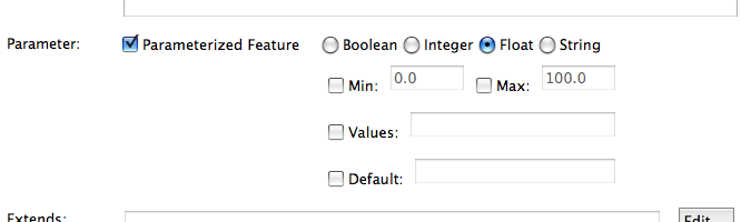
As you can see, we could also define a minimum and maximum value here or provide a default value. But we do not
want this in our case.
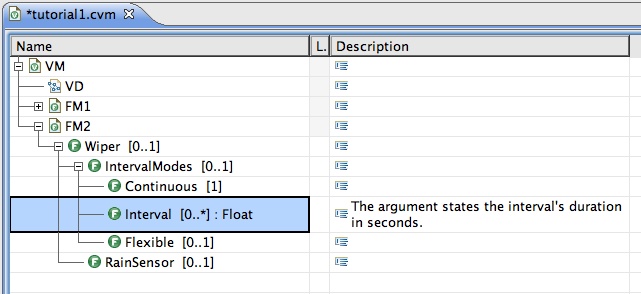
- Add an informative description to feature "Interval" by double-clicking the corresponding
cell in the model editor.
At this point you should have this:
Let us now add a final detail to our feature model: a dependency. For this purpose, we assume that feature
"RainSensor" may not be combined with the "Flexible" interval mode (for some technical reason). Such a
dependency or constraint is realized in CVM by way of a FeatureLink:
- Select feature "RainSensor".
- If the properties view of Eclipe is NOT visible right now:
Right-click feature "RainSensor" (in the model editor!) and select "Show properties view" from the context menu.
- In the properties view choose tab "Links"
--> the properties view now shows a list of feature links to/from feature "RainSensor" (should be empty for now).
- Click on button "Create ..." (in the properties view).
- In the dialog that shows up: select the target feature for the new feature link, i.e. "Flexible" in our case.
- Click "Ok"
--> the new feature link should now have appeared in the list.
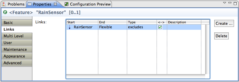
- Change the type of the newly created link to "excludes" and set a check-mark in column "<->" to make it
bidirectional (both can be edited directly in the table).
Your properties view should list a single feature link now, as shown here:
Configuring Feature Models
So let us configure this feature model now:
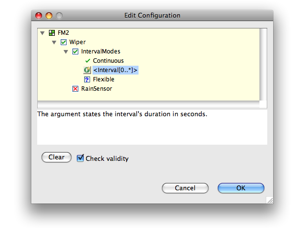
- Right-click feature model "FM2" in the model editor and select "Configure ..." from the context menu.
- Edit the configuration in the configuration dialog that shows up (see screenshot below).
- If you click "Ok" on leaving the dialog, then a new feature configuration will be created that captures the configuration edited in the dialog.
If you right-click an existing feature configuration instead of a feature model and select
"Configure ..." from the context menu, then you can edit this existing configuration instead
of creating a new one.
Configuration Links
Several feature models can be linked with respect to their configuration by way of a so-called
configuration decision model. This means with the information captured in a configuration
decision model it is possible to derive configurations of one feature model, called target feature
model, from valid configurations of another, called source feature model. Such an
arrangement of source and target feature models linked together by a configuration decision model
is also called a configuration link.
The actual elements for defining how to configure the target feature model depending on the
configuration of the source feature model are called configuration decisions. As the
name suggests, a configuration decision model is made-up of many configuration decisions.
To illustrate this, let us create a simple configuration decision model:
- In the model editor, right-click the root variability model "VM" and select
"New Child / Config Decision Model" from the context menu.
- Double click the newly created element's name and enter "CDM" as the new name.
- We now have to define the source and target feature models linked by our new config decision model:
Right-click element "CDM" and select "Edit Source & Target Feature Models" from the context menu.
- In the dialog that opens, select "FM1" from the tree view; then click button "Add as Source";
in the "Set Name" dialog that opens up, confirm by clicking button "Ok" without entering a name.
- Similarly, select "FM2" from the tree view and click button "Add as Target" and again confirm with "Ok".
Now you should see something like:
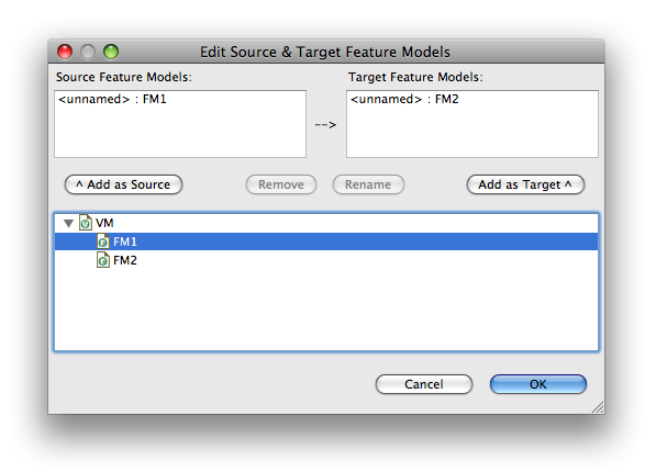
Note that we could provide local names for the source and target feature models that reflect
their precise role within the configuration link we are currently defining. In our simple
example, however, we do not need this. (Remark: with such explicit naming we can even use
the same feature model more than once as source or target, for example to create two distinct
target configurations for the same feature model.)
- Click button "Ok" in the dialog to get back to the main model editor.
We have now created a configuration decision model called "CDM" with "FM1" as source and "FM2" as
target feature model. The next step is to actually define how to configure "FM2" depending on a
given configuration of "FM1":
- Right-click "CDM" and select "New Child / Config Decision" from the context menu.
This creates a new configuration decision, i.e. a conditional rule how to configure "FM2".
For the next steps, please make sure you are in the model editor's grid view by clicking
the 'Grid' tab on the lower side of the editor window.
- In the row of the new element, double-click the cell in the first table column and enter
"Advanced OR Automatic". This is an expression in propositional logic on the configuration of
"FM1" that states when this rule shall trigger, i.e. have an effect on the configuration of "FM2".
- In the row of the new element, double-click the cell in the table column called "Included
Features" and enter "Flexible". This is the configuration decision's
effect in the form of a list of features to be selected whenever the condition in column one
(cf. step 2 above) evaluates to true. In this case we just state that feature "Flexible" is
to be selected.
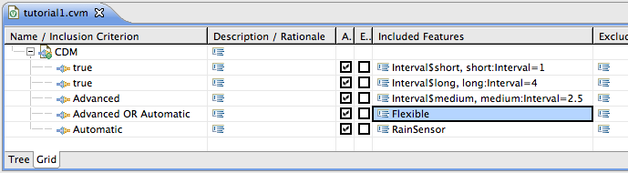
- Repeat steps 1 through 3 to obtain five configuration decisions with the following information:
| Criterion (step 2) | Effect (step 3) |
|---|
| #1 | true | Interval$short, short:Interval=1 |
| #2 | true | Interval$long, long:Interval=4 |
| #3 | Advanced | Interval$medium, medium:Interval=2.5 |
| #4 | Advanced OR Automatic | Flexible |
| #5 | Automatic | RainSensor |
The criterion "true" is used to define defaults that are always applicable. The effects of
configuration decisions #1 to #3 are special in that they not merely select an optional
feature but create instances of cloned features and assign values to them.
Now, your editor window should look something like this:
With these configuration decision we have defined how to configure "FM2" depending on a given
configuration of "FM1": we always have two default intervals "short" and "long"; the advanced
version of the wiper gets an additional medium interval; the automatic variant, represented
by feature "Automatic" in "FM1" gets a rain sensor; finally, the flexible interval denoted
by feature "Flexible" in "FM2" will be selected both for the advanced version of the wiper
and the automatic variant (and the case of an automatic advanced wiper, of course).
To try out interactively this newly defined configuration link you use a dedicated view of
CVM called "Configuration Preview":
- If the configuration preview is not open yet, select "Window / Show View / Other ..."
from the main Eclipse menu. In the dialog select "Configuration Preview" and click "Ok".
- Place this view below the main editor window.
- Select configuration decision model "CDM" in the editor.
(Note: do not select an individual configuration decision because this will put the
configuration preview in editing mode.)
The preview now shows the source feature model "FM1" on the left and the target
feature model "FM2" on the right:
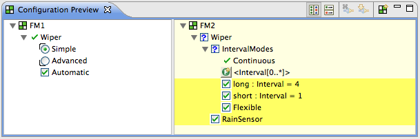
You can edit the left side and the right side will automatically be updated with
the configuration derived from the one you edited on the left. The above screen-shot
shows the configuration of "FM2" for the Simple variant of the wiper with "Automatic"
feature: no special medium interval but "Flexible" and "RainSensor" are selected.
A yellow highlighting the effects of the configuration link took place. Play around
with the configuration on the left and verify that the configuration on the right is
updated correctly through the configuration link.
CVM provides much more support for editing configuration decisions and for automatically
deriving target configurations from given source configurations. Furthermore, it is
possible to define configuration graphs, i.e. complex networks of configuration
in which the nodes represent feature models and the edges are realized by configuration
decision models. However, this detail is beyond the scope of this overview tutorial.
Textual Variability Specification
Finally, let us examine how our sample variability model would look like in the textual variability
specification language VSL.
For this, we can now close the model editor. So,
| Plugin Version | | RCP Version |
- Close the CVM model editor.
- In the view called "Navigator" or "Package Explorer" find the ".cvm"-file we have created above.
- Right-click it and select "Convert to .vsl" from the context menu,
--> a new file with the same name but extension ".vsl" will be created.
- Now double-click this new ".vsl" file,
--> the VSL editor will open.
| |
- NOTE: In the RCP version, the context menu action for converting from ".cvm" to ".vsl" files is not available yet.
Therefore you need to create a new ".vsl" file with a sample model for now, so ...
Select from the main menu "File / New VSL File ...".
- Choose a folder and file name in the dialog and click "Save".
- Select to create a file with a sample model.
|
This is what you should see now:
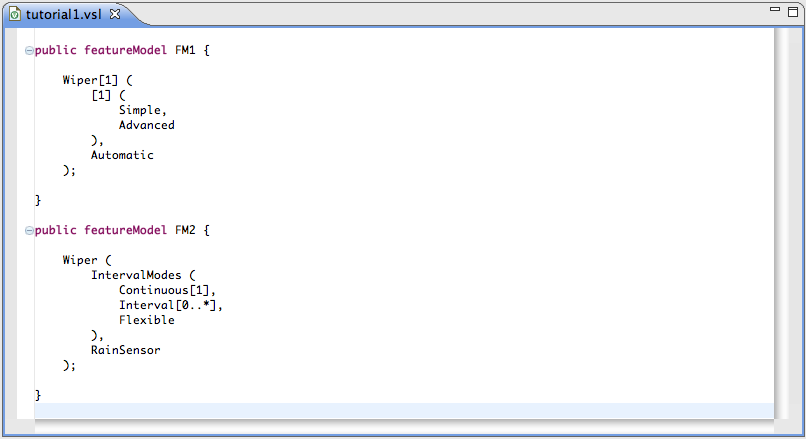
NOTE: The code in this screenshort was simplified for illustration purposes.
In the editor window that opened up, you can see the VSL code of our small example from above.
We won't go into detail of the syntax of VSL here, but you can experiment with the syntax in
the editor. Whenever you save the file, the syntax will be checked and errors will be highlighted.
Summary
We have seen how to create feature models in the model and diagram editor and how to configure
them and store the configurations. We have also examined how to link two feature models with
respect to their configuration by way of configuration links. Finally, the alternative textual
representation using the variability spefication language was briefly presented.